What about driving it at full tilt in A2?:

The driving signal has to be about 160Vpp to provide maximum swing, so power is:


H2 distortion:

Which yields a whooping 6%!
All about electronic valves and hi-fi

What about driving it at full tilt in A2?:
The driving signal has to be about 160Vpp to provide maximum swing, so power is:
H2 distortion:
Which yields a whooping 6%!
Ok, the previous operating point wasn’t optimal from a musicality perspective. As suggested by 45, I reworked the load line for 36mA/275V and anode load of 5.6KΩ (which is what I could get with my OT):
 The driver should now provide
  .
.
The output power will be around:

Efficiency would be around 36% in theory. Happy if around 3W can be obtained from this valve here with a reasonable distortion…
On the previous post I explored how more power could be extracted from the 45 in class A2. Here is a first draft circuit using the 4P1L as the driver stage with a mu-follower gyrator load to provide current with low output impedance:

3.5W can be obtained with 13Vpp input signal. Clearly a pre-amp is required, but that is the output level I’m currently getting from my preamp so should be fine. The LND150 CCS reference can be optimised and derived from the stable 280V.
Not a bad idea, just an additional power supply to avoid any nasty cap in the path.

Having had a great exchange of comments with “45” in a previous post, I thought it was easier to post this after doing some simulations with the 45 DHT in A2 operation.
I’m a great fan of the 45 valve. I think is probably the best sounding DHT out there. I listened to 300B, 2A3 and even 4P1L as an output valve, but nothing compares to me to the warm sound of this valve.
Later specifications of the 45 show that you can push it to 10W of anode dissipation. I’m currently using it at Ia=34mA, Vak=300V with an 2.5KΩ OT. You could get 2W out, but at the moment I’m squeezing 1.5W at maximum drive. There is a way of getting more out of the valve which is obviously by driving it in A2 (i.e. positive grid current). My current project (4-65A SE in class A2) uses a gyrator-loaded driver and stacked supplies which work brilliantly in A2. The driver provides sufficient grid current at low impedance even when the input impedance of the output valve drastically changes when grid current kicks in closer to 0V.
I have a pair of LL1623/60mA which I’m planning to use in the future to try 4P1L PSE or 6C4C output stages. This OT can be configured for 5.6KΩ, 3KΩ and 1.6KΩ anode loads.
Here is a first simulation of the 45 operating in class A2. The bias point was changed now down to 210V/47mA as the OT is configured for 3KΩ load:
 The anode AC power is then:

So roughly for Iap=46.5mA and Za=3KΩ, then Pa=3.2W. This is about 32% efficiency. More than double of the current juice I’m getting out of this valve, but at the expense of pushing the grid to +32V and anode peak current of 93-94mA. Grid current should be around 3-5mA from what the AB2 data looks like.
Question is here, is it worth trying this? Complexity of the amp is on the stacked power supplies. The driver will need to swing easily 120Vpp, so a well designed 4P1L in filament bias can do this with minimum distortion.
Thoughts?

After a failed initial test which caused the silicon and the damping series resistor of the hybrid bridge to blow up due to a gassy NOS 6D22S, I burned in the valves for 30min and tested the supply with a dummy load.
Some few changes to the supply design included the replacement of the HV diodes with a series pair of 1200V@5A fast diodes. The filaments were referenced to cathode (+B) instead of ground to minimise Vhk and a snubber network formed of a pair of 100nF LCR 1.5kV capacitors across the input choke were added.
This is a hefty supply: massively heavy. The heaviest piece of iron I have built so far. Anyway, great decision to build this amp in a modular fashion, otherwise I would have need some mechanical aid for moving the stuff around and clearly my wife would have kicked me out of the house (she hasn’t seen this yet so the latter is yet to happen).

The load resistor is a pair of 3k3 50W aluminium clad ones bolted to an aluminium piece which at the same time is held by a vice (thanks Rod for the suggestion). This provides sufficient mass and heat dissipation capacity (need about 120W).
Initial tests were great, need to do some further ones.
here is the diagram so far:
Update 9th Feb 2013: Minor updates including rightsizing of the mains fuse and removal of earth switch as this supply will be used in floating mode
 Looking at improving the CX-301a preamp with cathode follower output I modified the gyrator load by replacing the DN2540 by a LND150 and 2SK170 which have a lower capacitance and will improve the performance. Likewise, the tail CCS now has low-noise audio transistors such as the KSC1845 and KSC3503. Bias point is roughly the same, a bit lower than before. Overall distortion in the simulation is great: THD<0.005% @ Vo=16Vpp and loading 100K and 330pF (cable load representation).
U2 could be 6Z52P, D3a or PC86. The latter will require and adjustment as the filament is 3.8V and not 6.3V.
I think is time for building and listening to a potential great preamp…
Lars requested the paralleled triode curves. Here they are:
 And the SPICE model which is more accurate than my previous version:
* Created on Sat Jan 19 15:50:19 GMT 2013 using tube.model.finder.PaintKIT
* model URL: http://www.bartola.co.uk/valves/
* Created by Ale Moglia 2013 [email protected]
*————————————————–
.SUBCKT TRIODE_3A5-2 SMALL 1 2 3 ; P G K ;
+ PARAMS: CCG=.9P CGP=3.2P CCP=1.0P RGI=2000
+ MU=12.46 EX=1.3857 KG1=1965.0 KP=132.0 KVB=1.875 VCT=-1.6 ; Vp_MAX=200.0 Ip_MAX=0.032 Vg_step=2.0
*————————————————–
E1 7 0 VALUE={V(1,3)/KP*LOG(1+EXP(KP*(1/MU+(VCT+V(2,3))/SQRT(KVB+V(1,3)*V(1,3)))))}
RE1 7 0 1G
G1 1 3 VALUE={(PWR(V(7),EX)+PWRS(V(7),EX))/KG1}
RCP 1 3 1G ; TO AVOID FLOATING NODES
C1 2 3 {CCG} ; CATHODE-GRID
C2 2 1 {CGP} ; GRID=PLATE
C3 1 3 {CCP} ; CATHODE-PLATE
D3 5 3 DX ; FOR GRID CURRENT
R1 2 5 {RGI} ; FOR GRID CURRENT
.MODEL DX D(IS=1N RS=1 CJO=10PF TT=1N)
.ENDS
*$
Looking at distortion, as expected the pair of paralleled triodes performs better than a single triode:


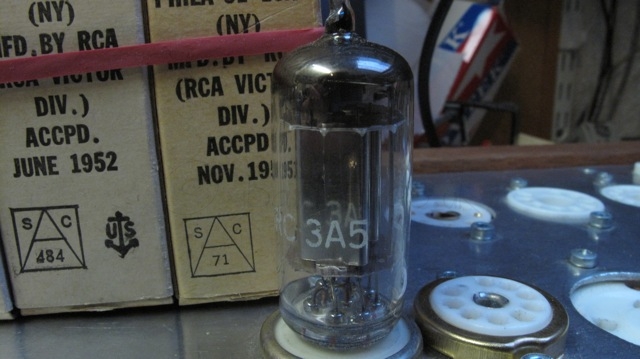
The 3A5 DHT is another interesting valve to bear in mind. Many have used them successfully even in a phono stage. Great examples are Dmitry Nizh’s DHT phono stage and Sheldon’s. I will probably use them as well at some point.
 Well, many DHT have been dismissed over the years due to their microphonic sensitivity. True, they are more microphonic, but this is manageable. Look at the 4P1L for example. I built a great preamp a couple of years ago and played around with the mechanics of the preamp to quiet it down. And I managed to, succesfully (as many have as well). The 4P1L sounds fantastic, despite so many turning it down because of its natural singing skills 🙂 Now, 4P1L is looked after, many are building DHT preamps and even full DHT amplifiers.
Looking at the specifications of the 3A5, we can see that the heater is attractive to be used with rechargeable batteries. Well, at least 220mA @ 1.4V is manageable. Key specs are:
How linear is this DHT? Let’s look at the curves first:

 After the initial tests done with the 4P1L in pentode mode and filament bias, I thought a bit about how this driver could be implemented in practice. I may try this configuration in my 4-65a SE amp, but am not urged by this at all.
The screen supply is formed by a gas valve (SG3S) which provides a very stable reference when feed by a CCS. In this case the cascoded pair M3 and M4 will provide in conjunction with R4 and U2 a very low noise screen current to U1. R9 has to be adjusted on test to set a current of about 15mA on the CCS. The 4P1L will draw 1.8mA at 81V as screen current, so R4 may also need adjustment to set the right operating point.
The driver should provide about a gain of 150. Driving easily a transmiting vale (or why not a 300B 🙂 ) in class A2 with this configuration. My tests showed a maximum THD of about 0.27% at 200Vpp.
Gain could be reduced if needed by tweaking the RL. And if stacked supplies are not used, then a single +400V supply could be used with additional dissipation across the reference currents (M1 and M3/M4).
Keep thinking…