I’ve been using my choke-input DHT filament supplies for many years. I’ve got many of them as you’d expect. Something I do really hate is to build power supplies. It’s dull and boring, but they’re a necessary evil. I’m afraid I have to admit.
Recently I experienced the dreaded smoke of capacitors blowing up. It’s actually funny in hindsight, however at the moment of the fireworks you don’t laugh. I killed one Coleman regulator as well with my experiments on a flexible DHT supply. That made me revise the design and the stress put on the components, in particular when you’re using filament bias in anger, as I do.
Anyhow, over the last 3 months I’ve been playing with SMPS supplies to try to get the commercial available ones quiet enough to be used with a DHT preamp. I started with classic filter stages like CLCLC, morphed to gyrator filtering (which wasted a lot of heat) and then resisted using LDO regulators which I knew it would do the trick. However, getting rid of the HF noise is a daunting task.
Actually, I have a variable HT SMPS supply built which sounds really good and is extremely quiet. It can deliver 2 channels of 600V/100mA. For a filament supply, the SMPS challenge is of a major league game. You can get the noise to about 1mVrms but the harmonics spread well over the mid and high range. Big chokes have also a big leakage capacitance which makes the choke not that effective at filtering off this HF noise. 1mVrms in 600V is fine, however 1mV in a 16V supply which si feeding the filament bias resistor is a problem.
After giving up, my patience these days isn’t the best I have to admit. In particular when time available for DIY audio is very limited. So I said to myself: “sod the SMPS, I will get a nice pair of custom made transformers with multiple taps and job done”. And that is what I precisely did. JMS transformers in the UK provide an amazing service. I’ve mentioned them in the past several times. I get all my power transformers from them these days. I ordered a pair of split bobbin, with outer copper screens and multiple taps to cater for all the voltage ranges needed for my output stages. From a 4P1L to a 300B.
As I always use choke input supplies for filaments, I used the LL2733s I have in stock and carelessly wired it on 400mH (series bobbins) which provides a huge voltage peak output when the minimum choke input current isn’t in place. This happens at start up, the voltage will raise to the level of cap input supply when the filament is just starting up thanks to the gentle raise of the Coleman regulator. The result is the high voltage peak output which can damage the capacitors.
The solution was to wind the input choke with the two bobbins in parallel to get inductance down to 100mH. Also the resistance is reduced significantly which avoid wasting too much voltage drop on the choke. Also adding a tuning cap (C3) to make the supply to operate in a hybrid mode between choke and cap input is great to dial in the output voltage.
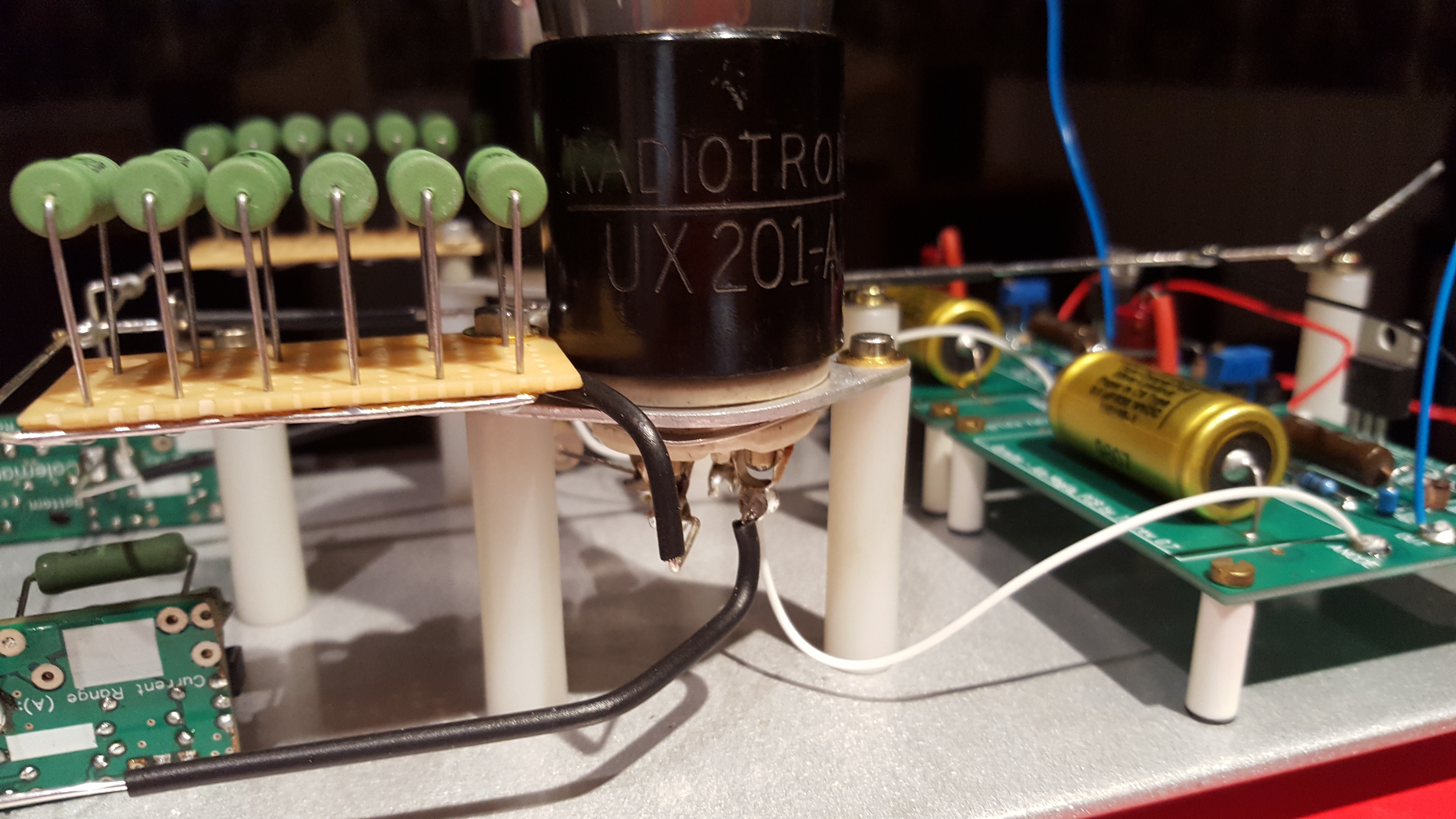
Here is my supply which I use for the VT-25 and the 4P1L preamps:
 Continue reading “A tale about DHT Supplies”


