Top plate arrived as well, so we can put the UV-201a DHT preamp in its final frame. Now it will be time for soldering, yay!


All about electronic valves and hi-fi

Top plate arrived as well, so we can put the UV-201a DHT preamp in its final frame. Now it will be time for soldering, yay!

It was time for the 10Y DHTs to do their beauty today. Sunday night with good music and single malt. Nothing more can be asked!
Well, after enjoying the 2P29L as part of the Mule preamp project, I decided it was worth building it so I can continue with my adventures on the DHT land. The 2P29L sounds so good that is worth having it as a standing preamp so here is my new version in progress. Thanks DHTRob for your inspiration using the IKEA chopping boards in a slightly different way I used them so far:

Simple and neat. The 2P29L were stripped out of their aluminiun cans. Naked as when we come to life. The gyrator boards are ready and tested. Just need to get the Rod Coleman regulators and complete the wiring.
Happy DIY audio!
I’ve been posting not very frequently lately. This is mainly due to lack of time and the level of business travel which reduced to nearly none the time available for DIY audio.
Nevertheless, the scarce time always pays off. It’s incredible how selective I have to be in order to prioritise which project I should work on. The list is long though.
Last time I did a quick exercise on the Ba DHT based on the curves I traced and the LTSpice simulation. Well, you always need to build and test in order to check against simulations. The result is, that you may need to adjust and learn from your practical experiences.
The Ba (like the Aa) are tricky to use. They pick up any electrostatic induced noise. You don’t need even to place your hand close, the mains noise is induced already in its plate. This force you to shield these valves if you want to use them. Am afraid, that is what it is. My friend Rob (DHTRob) warned me, thank you.
The circuit I posted here, had to be readjusted. Distortion was way too high. The operating point wasn’t good enough. You’d normally get inclined to run the valve as hot as you can, but I was wrong here with this one.
Travelling around Europe on business is paying its toll. I’m away from home every week and pretty exhausted now. I don’t have much time free and whatever is available I spend with my family. Hence, the lack of posts recently. I hope this will change in the future.
Anyway, what’s up in the DHT world? I listened the Aa/Ba valves long time ago but never played with them. Mainly due to their higher anode resistance. With the gyrator load and the source follower output, things take a different dimension.
I have a nice stash of Aa from Valvo (globe) and Ba from Siemens. Interesting to see that curves are not easy to find, so I submit them both to the mercy of the uTracer. Nice to see the linear curves with high mu about 14 on the Ba to 30 in the Aa.
Here is an example of the Ba loadline:

I’ve been playing for some weeks the marvellous UV-201a stage. The addition of the source follower brings a new dimension to this stage. However, I experienced random oscillation on this setup. I knew it was the MOSFET, but I wanted to pin it down.
I replaced the SiC version with the famous AOT1N60. That cure the issue, but I wanted to find out what was going on, of course blaming my selection of gate stoppers.
Some time ago, I did some initial experiments with the 4P1L (4П1Л) with the screen performing as anode instead. Some DIYers claim the improved sound of the mesh type anodes. Kees Brakenhoff kindly sent me some PL519 to test in screen mode. He has done multiple builds with this mode of operation with great results. Unfortunately I’ve not had the chance yet to build such an amp.
What I could do instead though, was to mod very quickly my 4П1Л preamp to screen mode. It was a very easy and fast modification. I kept the same heating wiring and just adjusted the screen (anode) current down to 10mA: Continue reading “4P1L / 4П1Л Siberian Gen4 in Screen mode”

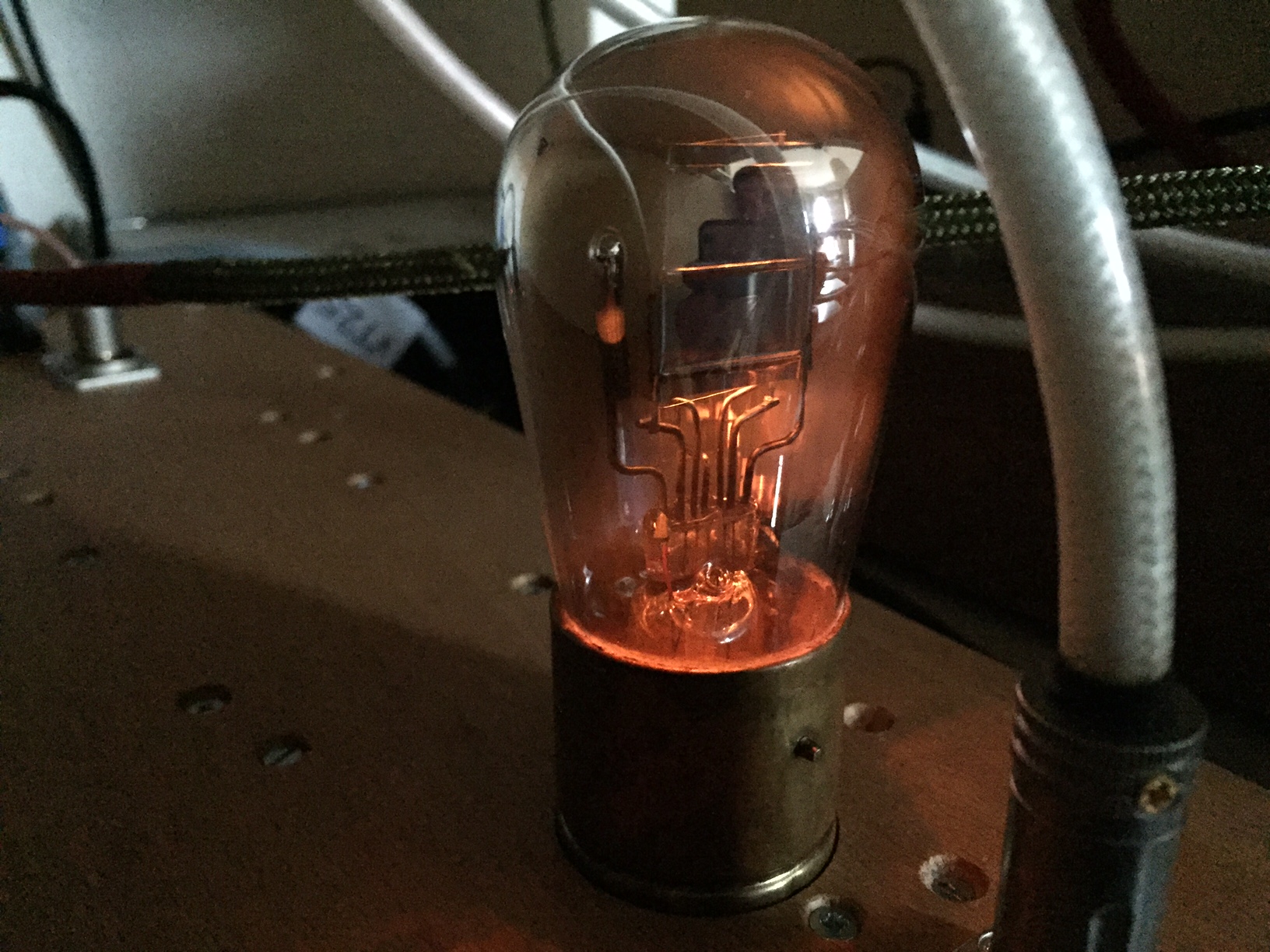
I previously implemented a preamp with the UV-201a. These are very old globe valves, somehow fragile and hard to get in good shape. Despite all this, it’s a superb valve. I have managed to acquire a decent set of them to pair the best valves to use in my preamp.
Recently I developed a prototype PCB for the source follower circuit. The source follower is ideal to place at the output of this preamp due to its low driving current. My 4P1L PSE amplifier will be pleased with more current to pump the Miller capacitance effectively.
I’ve been posting about the use of source followers in the circuits with some interesting results from testing. Some interesting posts to read, If you haven’t read them so far:
After several tests over a variety of circuits, I finalised the prototype for a Source Follower PCB. The circuit is incredibly useful. Some examples of uses cases are:
Some key aspects of the board are:
Here is one of the boards submitted to the usual abuse during testing:

This is a very useful PCB in my view which can be used extensively in preamps, line stages and amplifiers.
If there is sufficient interest, I will run a batch of PCBs for the DIY audio community:
The gyrator PCB has been updated to fit now a wider variety of lower enhancement MOSFETs with low capacitance and high transconductance. The best examples are the BSH111BK and BSN20BK which are great options for currents above 25mA:

The board offers now all the flexibility needed in terms of different TO-92 and SOT-23 package pin-outs to use whatever FET you want.