eTracer Build and Review

Tracing valves: an obsession

Since my early days of valves and DIY audio, I developed an obsession around testing and tracing valves. This led me to design and build my analogue curve tracer which I used for many years successfully until I build my uTracer, which was a great innovation in curve tracing. I do have many valve testers (some which I made myself) so why building another one?

Well, Chris Chang from Essues Technologies developed a fantastic new digital curve tracer for valves, the eTracer.  There are a few things which will grab anyone’s attention on this curve tracer. Firstly, the power supplies can accommodate a large range of valves which the uTracer can’t. HT can go as high as 750V @ 300mA and the grid supply down to -170V! This is exactly what you need to test your transmitting valves or even a 300B.  Secondly, the tracing speed is surprisingly fast. This is a nice feature, specially when you want to trace pentodes at various screen voltages to develop a Spice model  for example. 

Build process

Continue reading “eTracer Build and Review”

Valve Leakage Test

Years ago when I built my analogue curve tracer I added a small, yet very effective valve leakage test circuit. Due to my laziness, I failed to test a  transmitting tetrode which I bought on-line and despite being NOS it damaged my uTracer. I followed the repair and re-calibration process and got the tester back again running, however, I regretted not having used this simple one step test I normally did before.  Lesson learned, now I do use it back again!

Here is the circuit in case you don’t have a proper tester and you want to build something similar yourself:

leakage tester publishedYou can test for leakage current using a simple amplifier made out of a NPN transistor and an indicator. In this case I used a Russian Neon (80V/0.5mA) and the existing supply on my tester (+/-80V). You can replace all this with a simple LED and the supply you have at hand. The circuit is designed to turn on the bulb when 5 μA leakage current is provided on the base of Q1 thanks to grounding the valve element next to the one under test. So for example if we want to measure cathode to grid leakage, we simply ground the cathode and we connect the tester to the grid. Same process is repeated with the other valve elements.

When I asked for some help in the DIYAudio forum, someoone gently recommended this text. Unfortunately I don’t read German, but what I got out of this adivce was:

  1.  valves with poor vacuum (i.e. failed the test described on the procedure in 18A)
    1. preamp valves with less than 4 μA are usable
    2. output valves whit less than 10 μA are usable
  2. Valves that are good and show little Gas on the gas test:
    1. should have less than 0,6-1μA for preamp valves
    2. And should have less than 1.5-2μA for output valves

So the 5μA threshold was good enough in my view. It does work well and the beauty is that when neon light is very dim is an indication that it may be a workable valve despite the tiny leakage in particular with output valves.

Hope this helps

Ale


A versatile CCS load

I’m a heavy user of CCS loads. I generally use them to test my valves regardless of using my curve tracer or not. I tried multiple CCS types in the past with good results until I ended up burning one FET or protection zener or whatever due to the abuse of it.

Testing high current loads is not easy at high voltages. The DN2540 is rated at 400V. Not enough. You can use an expensive 01N100D which is another depletion 1KV MOSFET that has a lower Ciss (54pF against 200pF) or you can look at the cheaper enhancement FETs which require a different bias arrangement. If we are looking at modifying the classic cascode self-bias pair, it is a convenient opportunity to improve the VDS bias of the lower FET to improve the frequency response by lowering the Ciss. Remember that in a FET the Ciss is proportional to the VDS. The classic cascode pair has a disadvantage as the lower FET is biased with VDS lower than 1-2V to ensure the upper FET is biased correctly.

Continue reading “A versatile CCS load”

Valve Tracing & Testing Service

If you are looking to test your precious valves and you don’t have the equipment, I can now offer this service for you which includes:

  1. Valve health check
  2. Valve bias point measurement (Ia, Is @ Va, Vs)
  3. Transfer curves
  4. Characteristic curves
  5. Microphony (optional)
  6. Distortion – THD (optional)
  7. SPICE model for triodes (optional)

20130929-202754.jpg


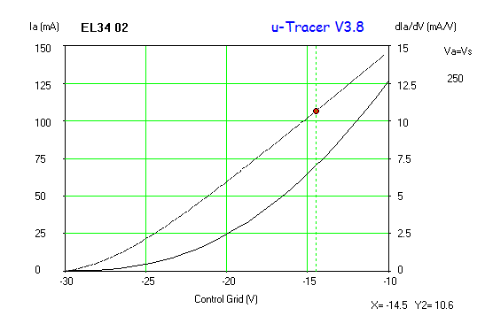
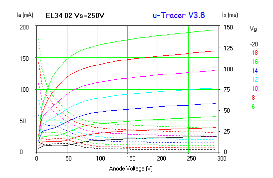
Some examples of a lovely EL34 Mullard tested on request:

EL34 02 EL34 02 Vs=250V

My fees are very competitive and this service is worth if you are looking to sell your valves or match them.

Terms and conditions:

  1. Price varies on level of testing and amount of valves
  2. Postage is not included and depend on your location. I’m in London, UK so you can easily estimate the costs beforehand.

Update – August 2021

My apologies but due to pandemic and lack of free time, I’m not offering this service anymore.

Transconductance tester

Introduction

IMG_0580For some time I’ve been postponing the conclusion of a half-finished project. This is one of the many projects that I have around as many of you, but it was time to complete it as just some minor bits were outstanding.

My interest in measuring valve transconductance was very high since my early days of involvement with hollow state technology. The old valve tester I acquired didn’t measure it, I tried many ways to measuring it with different methods until I settled with using a CCS load and an AC meter as described here.

The problem I found though was that my true RMS AC meter in low scale (i.e. 100mV AC) didn’t like a significant DC voltage drop across the sensing resistor. Not sure why, but either way I wasn’t happy either without decoupling the anode to the sensing part of the circuit when using high voltages.

Continue reading “Transconductance tester”

4-65a EIMAC

4-65a EIMAC NOS DHT

Just got a couple of NOS EIMAC which I will be using in my SE design

4-65a EIMAC NOS

So did some test on distortion, transconductance and driving them to +22.22dBu output to check the quality of these two ones.

I used similar test rig as before. At some point will be able to get a proper filament supply for this valve, but for the time being I will continue to use the hum pot and the big electrolytic cap across my old bench power supply which can gently provide the 3.5A for the hungry filaments!

I tested them at the limit of my CCS and bench HT supply which at the moment cannot provide more than 360V @ 100mA.

Transconductance is in the region of 3,800 – 4,000 μmhos.

So biasing the valve at -2.5V and over 90mA of anode current, the harmonic profile looks like this:

4-65A NOS EIMAC

Both EIMAC measured about 0.12% THD.


VT-25 / 10-Y triode curves

VT-25 triode curves 


Everyone loves this thoriated-tungsten DHT valve. I’ve only used it in a preamp and was hooked with its sound. Really warm and nice. Downside is, it’s very pricey these days and also is quite demanding from a filament perspective.  You can check the characteristics here.

For those who like testing their designs with LT SPICE, I produced a model which matches really well the traced curves. Would like anyone to use this one, to drop me a note with any feedback 🙂


RCA10Y VT25 spice model

Here is the VT-25 spice model. Let me know how it works for you!


46 THD analysis

GM tester modified today to add an option to disconnect the CCS bypass capacitor so can drive the valve with an external signal and measure THD from output in common-cathode mode. The input is calibrated to produce 10Vrms (22.22dBu) at the anode and then signal is fed into the PC through the Pete Millet’s interface:

GM/THD tester

Did some sample tests with a set of lovely globe CX301a achieving THDs from 0.27% to 0.35%.

When looking at a driver valve such as 46 (triode-strapped) got THD values of around 0.05-0.09% for good valves. When picked up the faulty one I had discovered yesterday with the curve tracer, the THD shown to be 0.20% and over 0.35% in the worst one.

Need to retake these measures as the soundcard interface got damaged and results are showing significant distortion


20120604-122936.jpg
46 THD analysis

The PC generates a low distortion sine wave which is fed into the valve grid through the input capacitor. This is the same setup used for the transconductance test. The CCS in the anode is unbypassed to ensure the anode signal is not shunted to ground. The output is then taken out through the output PIO capacitor and fed back into the PC input adapter (Pete Millett’s sound card interface). Audiotester is used then to measure THD at 1kHz.

20120604-122954.jpg

Measuring valve transconductance

Today I breadboarded the CCS I will use for the transconductance tester jig which is an addition to my curve tracer:

20120527-130504.jpg

Bias circuit is a classic from fixed bias amplifiers. I had the 80V available from the curve tracer circuit. The meter is an external panel AC voltmeter which is a trueRMS meter that will measure accurately the 1kHz signal.

The MOSFET CCS is a simple cascoded which can help setting the valve current and operating point. I source it with my bench variable HT power supply, which also helps in setting out the operating point.

We know that we need to have a small AC signal in the grid to increase the accuracy of the Gm test as the transconductance is given by:

G_{m}=\frac{\Delta I_{a}}{\Delta V_{g}} _{\Delta V_{a}=0}

So can’t feed with 1Vrms, so will use 100mVrms. If a valve has a transconductance of 1mA/V, then the variance in the anode current will be of 100uA (rms). This represents a challenge to measure accurately using an anode resistor of 10 ohms for example since the developed AC voltage across the resistor will be 1mV (rms). Therefore we will use an anode resistor of 100 ohms which will help capturing small transconductance values as this one.


Edit:

Found that the CCS bypass was omitted in my first circuit. Also the sensing resistor was reduced to 10 ohms to accommodate the AC true-rms meter I have. See updates on this post here